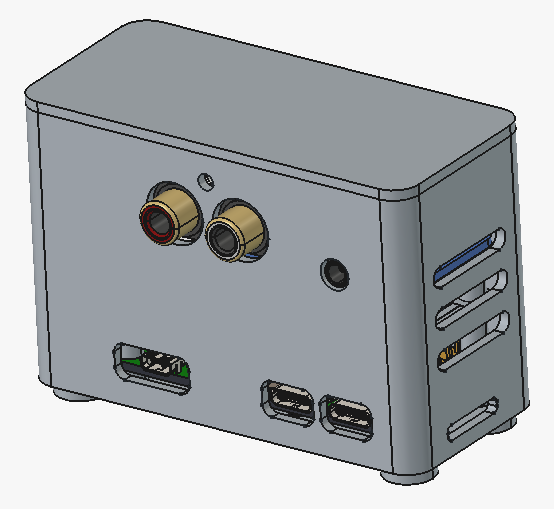
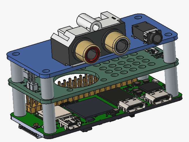
hello everyone and @MichaIng
I ordered and received a Radxa Zero 3W to pair with my Waveshare PCM5122-based PCB.
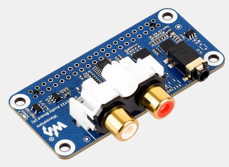
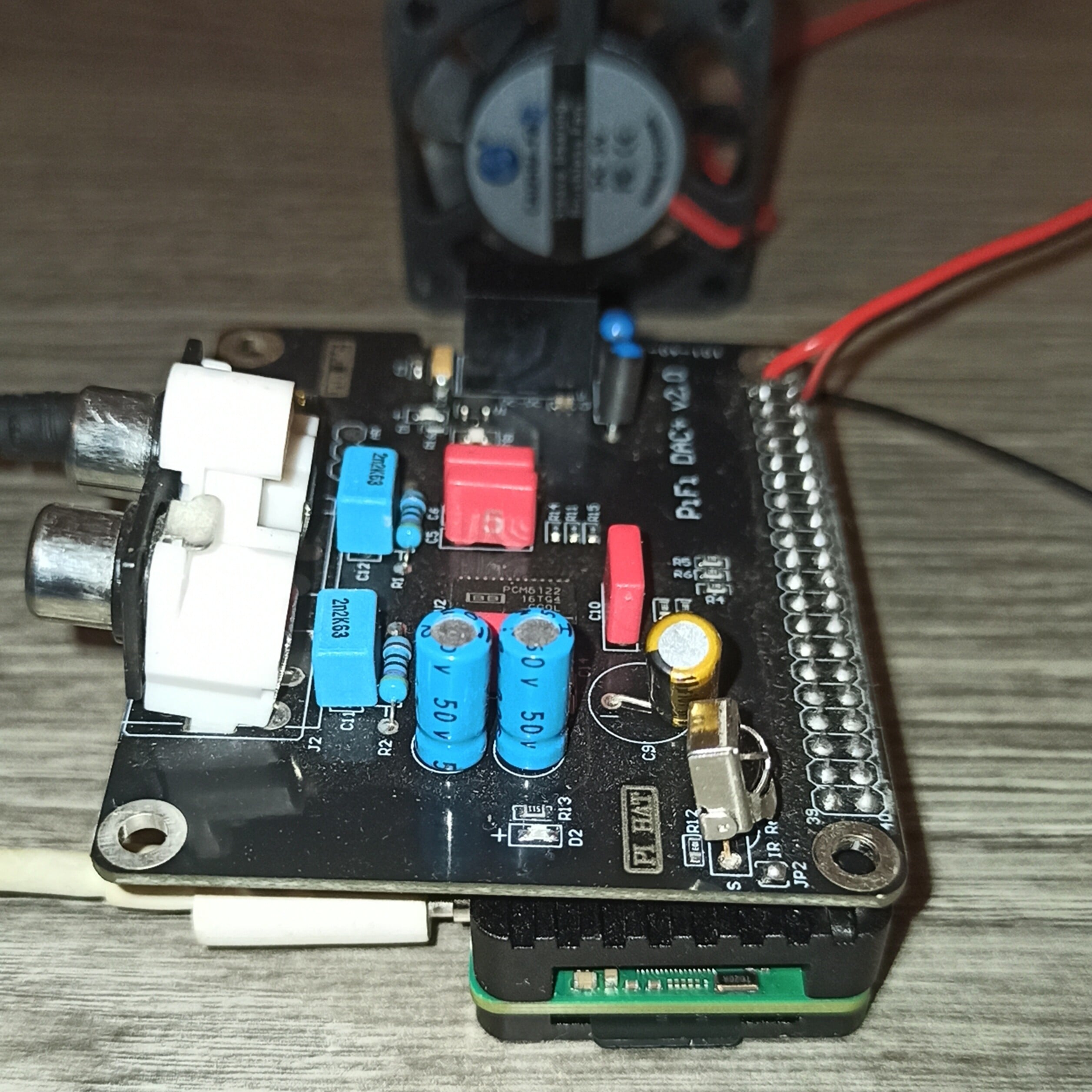
Since the chip is a Rockchip RK3566 and the board’s datasheet specifies that the I2C3 and I2S3-M0 buses are accessible via the 40-pin header (on pins 3, 5, 12, 35, and 40),
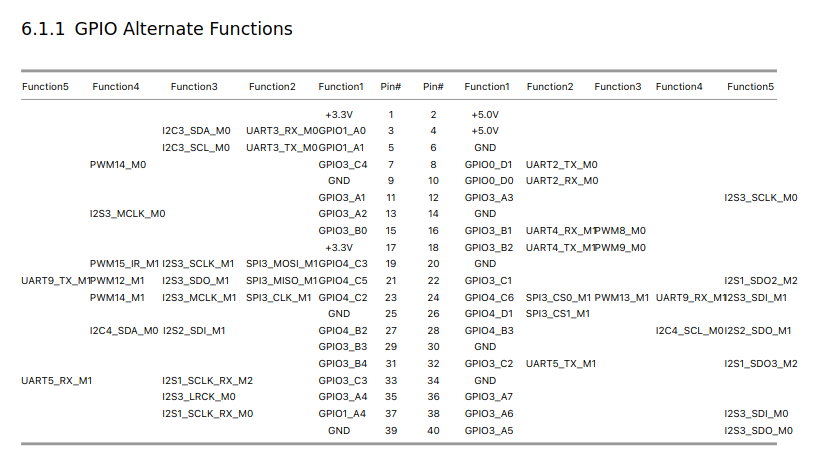
all that remained was to create a script to set up the DAC. This wasn’t exactly straightforward, as the Zero 3W is quite unique; however, below is a working script for the RCA outputs,
#!/bin/bash
# ==============================================================================
# SCRIPT UNIFIÉ ULTIME v3 : RADXA ZERO 3W + PIFI DAC+ (PIN 16/18 NATIVE FIXED)
# ==============================================================================

mkdir -p /boot/overlay-user
cd /boot/overlay-user

echo "--- [1/5] Réécriture du fichier d'environnement de Boot ---"
sed -i '/overlays=/d' /boot/dietpiEnv.txt
sed -i '/user_overlays=/d' /boot/dietpiEnv.txt

echo "overlays=hk-i2c0" >> /boot/dietpiEnv.txt
echo "user_overlays=pcm5122_i2s" >> /boot/dietpiEnv.txt

echo "--- [2/5] Création du script d'initialisation (I2C PCM5122) ---"
cat << '_EOF_' > /boot/overlay-user/init_dac.sh
#!/bin/bash
sleep 4

# Sélection de la page 0 des registres fondamentaux
i2cset -y 3 0x4d 0x00 0x00
sleep 0.1

# Sortie du mode Standby
i2cset -y 3 0x4d 0x02 0x00
sleep 0.1

# ROUTAGE PLL : Force le PCM5122 à utiliser le BCLK comme source MCLK
i2cset -y 3 0x4d 0x0e 0x08
sleep 0.1

# Ignorer l'absence d'horloge maîtresse externe (MCLK)
i2cset -y 3 0x4d 0x25 0x08
sleep 0.1

# Configuration de la PLL automatique et format I2S standard
i2cset -y 3 0x4d 0x04 0x00
sleep 0.1
i2cset -y 3 0x4d 0x28 0x00
sleep 0.1

# DÉSACTIVATION DE L'AUTO-MUTE
i2cset -y 3 0x4d 0x41 0x00
sleep 0.1

# Configuration et passage à l'état haut des GPIO internes du PCM5122 (RCA)
i2cset -y 3 0x4d 0x08 0x3f
i2cset -y 3 0x4d 0x09 0x00
sleep 0.1
i2cset -y 3 0x4d 0x54 0x11
i2cset -y 3 0x4d 0x55 0x11
i2cset -y 3 0x4d 0x56 0x11
i2cset -y 3 0x4d 0x57 0x11
sleep 0.1

# Configuration volumes (0dB) et retrait des mutes du PCM5122
i2cset -y 3 0x4d 0x3d 0x30
i2cset -y 3 0x4d 0x3e 0x30
sleep 0.1
i2cset -y 3 0x4d 0x6c 0x00
sleep 0.1
i2cset -y 3 0x4d 0x03 0x00
sleep 0.1

echo "Initialisation des registres I2C terminée."
_EOF_

chmod +x /boot/overlay-user/init_dac.sh

echo "--- [3/5] Réinstallation et activation du service Systemd ---"
cat << '_EOF_' > /etc/systemd/system/init-dac.service
[Unit]
Description=Initialisation et routage PLL du DAC PCM5122 via I2C3
After=sound.target i2c-dev.target
DefaultDependencies=no

[Service]
Type=oneshot
ExecStart=/boot/overlay-user/init_dac.sh
RemainAfterExit=yes

[Install]
WantedBy=sysinit.target
_EOF_

systemctl daemon-reload
systemctl enable init-dac.service

echo "--- [4/5] Écriture de l'overlay DTS (Libération PWM + Forçage GPIO 3.3V) ---"
cat << '_EOF_' > /boot/overlay-user/pcm5122_i2s.dts
/dts-v1/;
/plugin/;

/* Désactivation des blocs PWM pour libérer les broches 16 et 18 */
&pwm8 {
    status = "disabled";
};

&pwm9 {
    status = "disabled";
};

&{/} {
    pcm5122_sound {
        compatible = "simple-audio-card";
        simple-audio-card,name = "Radxa-PCM5122";
        simple-audio-card,format = "i2s";
        status = "okay";

        simple-audio-card,bitclock-master = <&cpu_dai>;
        simple-audio-card,frame-master = <&cpu_dai>;

        cpu_dai: simple-audio-card,cpu {
            sound-dai = <&i2s3_2ch>;
        };

        simple-audio-card,codec {
            sound-dai = <&pcm5122_codec>;
        };
    };

    pcm5122_codec: pcm5122-codec {
        compatible = "linux,spdif-dit";
        #sound-dai-cells = <0>;
        status = "okay";
    };
};

&hdmi_sound {
    status = "disabled";
};

&i2s3_2ch {
    #sound-dai-cells = <0>;
    rockchip,clk-trcm = <1>;
    pinctrl-names = "default";
    pinctrl-0 = <&i2s3m0_sclk &i2s3m0_lrck &i2s3m0_sdo &jack_pins>;
    status = "okay";
};

&pinctrl {
    pins {
        jack_pins: jack-pins {
            /* Force GPIO3_B1 (pin 16) et GPIO3_B2 (pin 18) en GPIO Sortie Haute (Pull-Up) */
            rockchip,pins = <3 9 0 &pcfg_pull_up>,
                            <3 10 0 &pcfg_pull_up>;
        };
    };
};
_EOF_

# Compilation finale du binaire .dtbo
dtc -I dts -O dtb -@ -o pcm5122_i2s.dtbo pcm5122_i2s.dts

echo "--- [5/5] Création de la configuration ALSA pour le contrôle du volume ---"
cat << '_EOF_' > /etc/asound.conf
pcm.!default {
    type plug
    slave.pcm "softvol"
}

pcm.softvol {
    type softvol
    slave {
        pcm "hw:0,0"
    }
    control {
        name "Master"
        card 0
    }
}

ctl.!default {
    type hw
    card 0
}
_EOF_

echo "=============================================================================="
echo " CONFIGURATION RADXA ZERO 3W PRÊTE ET COMPILÉE !"
echo " Lancez maintenant la commande : reboot"
echo "=============================================================================="


# ==============================================================================
# pour l'activer
# nano deploy_pcm5122.sh
# ctrl +o et ctrl +x
# puis
# bash deploy_pcm5122.sh
# ==============================================================================
Along with a script to test the PCM5122 registers for automated verification.
cat << '_EOF_' > /usr/local/bin/check_dac.sh
#!/bin/bash
# ==============================================================================
# OUTIL DE DIAGNOSTIC AVANCÉ (V2) - PCM5122 AVEC ROUTAGE HORLOGES ET MUX
# ==============================================================================

VERT='\033[0;32m'
ROUGE='\033[0;31m'
JAUNE='\033[1;33m'
BLEU='\033[0;34m'
NEUTRE='\033[0m'

afficher_diagnostic() {
    clear
    echo -e "${BLEU}======================================================================${NEUTRE}"
    echo -e "${BLEU}          DIAGNOSTIC AVANCÉ - MATÉRIEL DAC PCM5122 & INTERFACES      ${NEUTRE}"
    echo -e "${BLEU}======================================================================${NEUTRE}"

    if ! i2cget -y 3 0x4d 0x00 b >/dev/null 2>&1; then
        echo -e "${ROUGE}[ERREUR] Le PCM5122 ne répond pas sur le bus I2C-3 à l'adresse 0x4d.${NEUTRE}"
        return 1
    fi

    REG_02=$(i2cget -y 3 0x4d 0x02 b)
    REG_6C=$(i2cget -y 3 0x4d 0x6c b)
    REG_72=$(i2cget -y 3 0x4d 0x72 b)
    REG_77=$(i2cget -y 3 0x4d 0x77 b)
    REG_0E=$(i2cget -y 3 0x4d 0x0e b)
    REG_25=$(i2cget -y 3 0x4d 0x25 b)

    VAL_02=$((REG_02))
    BIT_STBY=$(( (VAL_02 >> 4) & 1 ))
    BIT_PDN=$(( VAL_02 & 1 ))

    echo -e "\n${JAUNE}[1/5] ÉTAT DE L'ALIMENTATION GÉNÉRALE (Reg 0x02 : $REG_02)${NEUTRE}"
    if [ "$BIT_PDN" -eq 1 ]; then
        echo -e "  -> Statut global : ${ROUGE}ÉTEINT COMPLET (Powerdown actif)${NEUTRE}"
    elif [ "$BIT_STBY" -eq 1 ]; then
        echo -e "  -> Statut global : ${JAUNE}MODE VEILLE (Standby actif)${NEUTRE}"
    else
        echo -e "  -> Statut global : ${VERT}ACTIF (Prêt à fonctionner)${NEUTRE}"
    fi

    VAL_6C=$((REG_6C))
    MUTE_L=$(( VAL_6C & 1 ))
    MUTE_R=$(( (VAL_6C >> 1) & 1 ))

    echo -e "\n${JAUNE}[2/5] ÉTAT DES AMPLIFICATEURS DE SORTIE (Reg 0x6C : $REG_6C)${NEUTRE}"
    if [ "$MUTE_L" -eq 1 ] && [ "$MUTE_R" -eq 1 ]; then
        echo -e "  -> Amplis Gauche & Droit : ${ROUGE}MUTÉS / COUPÉS${NEUTRE}"
    elif [ "$MUTE_L" -eq 0 ] && [ "$MUTE_R" -eq 0 ]; then
        echo -e "  -> Amplis Gauche & Droit : ${VERT}OUVERTS (Prêts à émettre)${NEUTRE}"
    fi

    VAL_72=$((REG_72))
    BOOST=$(( VAL_72 & 3 ))
    echo -e "\n${JAUNE}[3/5] RÉGLAGE DU BOOST ANALOGIQUE (Reg 0x72 : $REG_72)${NEUTRE}"
    case $BOOST in
        3) echo -e "  -> Niveau de gain : ${VERT}Standard (0 dB) + Auto-Mute Intelligent Actif${NEUTRE}" ;;
        *) echo -e "  -> Niveau de gain : Mode Manuel / Personnalisé (${BOOST})${NEUTRE}" ;;
    esac

    VAL_77=$((REG_77))
    BIT_POMPE=$(( (VAL_77 >> 4) & 1 ))
    echo -e "\n${JAUNE}[4/5] ÉTAT DE LA POMPE DE CHARGE INTERNE (Reg 0x77 : $REG_77)${NEUTRE}"
    if [ "$BIT_POMPE" -eq 1 ]; then
        echo -e "  -> Pompe de charge : ${VERT}ACTIVE & STABLE (Tension négative OK)${NEUTRE}"
    else
        echo -e "  -> Pompe de charge : ${ROUGE}INACTIVE / ÉTEINTE${NEUTRE}"
    fi

    VAL_0E=$((REG_0E))
    VAL_25=$((REG_25))
    echo -e "\n${JAUNE}[5/5] ROUTAGE DE L'HORLOGE SYSTEME / CONFLIT GPIO${NEUTRE}"
    if [ $((VAL_0E & 0x08)) -eq 8 ]; then
        echo -e "  -> Source PLL (Reg 0x0E) : ${JAUNE}Forcée sur BCLK via GPIO4 (Explique le verrouillage du Reg 0x54)${NEUTRE}"
    else
        echo -e "  -> Source PLL (Reg 0x0E) : Standard / Externe (MCLK)"
    fi
    if [ $((VAL_25 & 0x08)) -eq 8 ]; then
        echo -e "  -> Sécurité Horloge (Reg 0x25) : ${VERT}Ignore l'absence de MCLK (Indispensable pour Radxa)${NEUTRE}"
    fi

    echo -e "${BLEU}======================================================================${NEUTRE}"
}

if [ "$1" = "loop" ]; then
    while true; do afficher_diagnostic; sleep 1; done
else
    afficher_diagnostic
fi
_EOF_
chmod +x /usr/local/bin/check_dac.sh
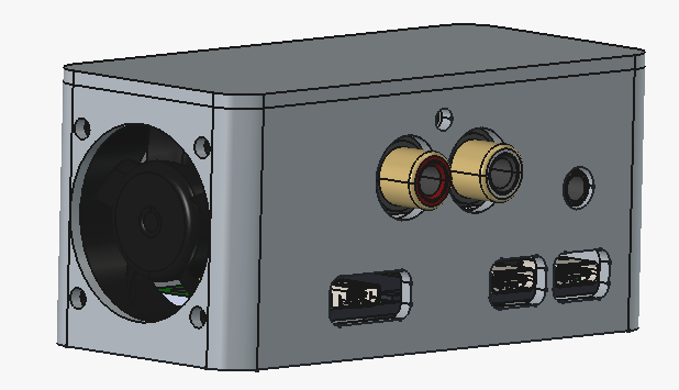
I still have one unresolved issue regarding the headphone jack on my test board (a PiFi DAC+ V2.0); since I’m on vacation, I only have headphones to test the audio output, and the chip handling the jack via the PCM isn’t responding.
It appears to be an issue with managing GPIO3-B1 and GPIO3-B2 (pins 16 and 18 on the 40-pin HAT connector specific to the PiFi DAC+ board).

 .
.