Orange Pi 3B with PCM5122 works together

Good evening everyone,

And a special hello to @MichaIng. I’ve had this idea in the back of my mind for a while, and the holidays provided the perfect opportunity to give it a try.

So, the initial idea was to get a commercially available SBC—something other than the ubiquitous Raspberry Pi—up and running as a high-quality audio server using a PCM5122 DAC. I found that the kernels available in DietPi for the RK3566 included the necessary pcm5122*.ko files, so I decided to go for it. An Orange Pi 3B SBC and a PiFi DAC+ fit the bill perfectly.
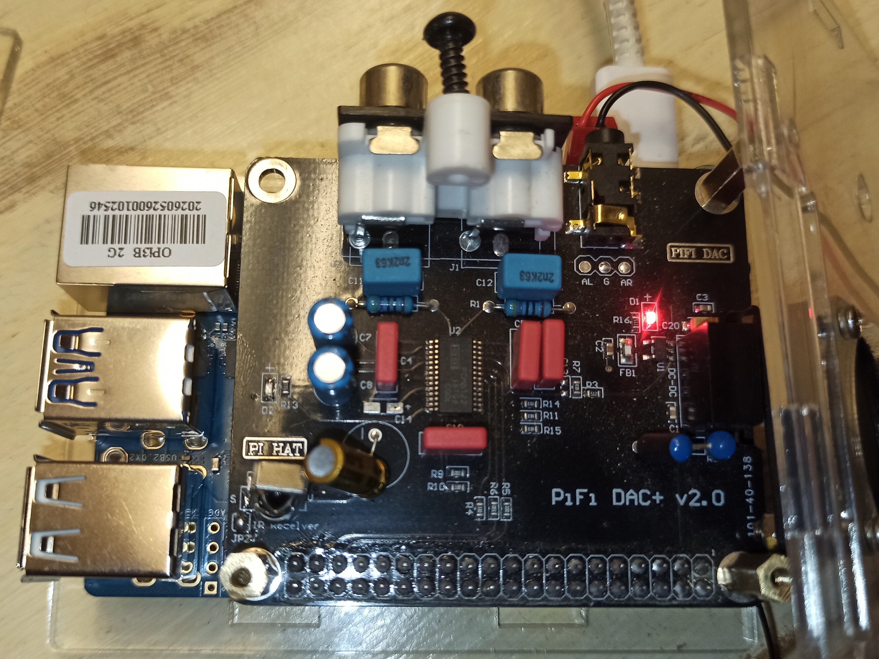

It wasn’t easy, but after many hours of research and various tests, I managed to get sound out of the PCM5122—something I believe hasn’t been done elsewhere.
To achieve this, I compiled all the steps into the script provided below. It handles enabling the I2S1 and I2C2 pins, configuring the PCM5122 chip via the I2C bus, and creating the service that manages this configuration when DietPi boots up. The script deploys everything needed in just a few command lines.
First, creating the script:

nano deploy_pcm5122.sh

Copy and paste this
Edit 09/08/2026 with modern version of DTS’s syntax and without sudo authorisation

#!/bin/bash
# ==============================================================================
# SCRIPT DE DÉPLOIEMENT UNIQUE AUTOMATISÉ : PCM5122 + I2C2-M1 FUSIONNÉS
# ==============================================================================

echo "--- [1/6] Installation des dépendances (i2c-tools & compiler) ---"
apt install -y i2c-tools device-tree-compiler

# Création et bascule dans le répertoire utilisateur
mkdir -p /boot/overlay-user
cd /boot/overlay-user
# Create the overlay source file
echo "--- [2/6] Création du fichier source unique (pcm5122.dts) ---"
cat << '_EOF_' > pcm5122.dts
/dts-v1/;
/plugin/;

/* Le symbole &{/} cible directement le nœud racine du système */
&{/} {
    my-soundcard {
        compatible = "simple-audio-card";
        simple-audio-card,name = "PCM5122NoMCLK";
        simple-audio-card,format = "i2s";
        status = "okay";
  
        simple-audio-card,cpu {
             sound-dai = <&i2s1_8ch>;
             dai-tdm-slot-num = <2>;
             dai-tdm-slot-width = <16>;
        };

        simple-audio-card,codec {
             sound-dai = <&codec_dummy>;
        };
    };

    codec_dummy: codec-dummy {
        compatible = "rockchip,dummy-codec";
        #sound-dai-cells = <0>;
        status = "okay";
    };
    sound {
        compatible = "simple-audio-card";
        simple-audio-card,name = "PCM5122NoMCLK";
    };
};

&hdmi_sound {
    status = "disabled";
};

&i2s1_8ch {
    #sound-dai-cells = <0>;
    rockchip,clk-trcm = <1>;
    pinctrl-0 = <&i2s1m1_sclktx &i2s1m1_lrcktx &i2s1m1_sdo0 &i2s1m1_sdi0>;
    rockchip,playback-channels = <2>;
    rockchip,capture-channels = <2>;
    rockchip,bclk-fs = <32>;
    status = "okay";
};

&i2s2_2ch {
    status = "disabled";
};

/* INTEGRATION CRUCIALE : i2c2 fusionné avec affectation des broches m1 (Pin 3 et 5) */
&i2c2 {
    #address-cells = <1>;
    #size-cells = <0>;
    pinctrl-names = "default";
    pinctrl-0 = <&i2c2m1_xfer>; /* Active physiquement les broches I2C2 multiplexage m1 */
    status = "okay";
};

_EOF_

echo "--- [3/6] Compilation de l'overlay unique (pcm5122.dtbo) ---"
dtc -I dts -O dtb -@ -o pcm5122.dtbo pcm5122.dts

echo "--- [4/6] Vérification du binaire via fdtdump ---"
fdtdump pcm5122.dtbo

echo "--- [5/6] Génération et enregistrement de l'initialisation I2C ---"
cat << '_EOF_' > /boot/overlay-user/init_dac.sh
#!/bin/bash
# Reset logiciel du DAC
i2cset -y 2 0x4d 0x01 0x11
sleep 0.2

# Configuration des registres pour mode esclave PLL (BCLK 16-bits strict)
i2cset -y 2 0x4d 0x02 0x10
i2cset -y 2 0x4d 0x25 0x08
i2cset -y 2 0x4d 0x0d 0x10
i2cset -y 2 0x4d 0x26 0x10
i2cset -y 2 0x4d 0x41 0x00

# Passage en mode actif et volume numérique à 100% (0 dB)
i2cset -y 2 0x4d 0x02 0x00
i2cset -y 2 0x4d 0x03 0x00
i2cset -y 2 0x4d 0x3d 0x30
i2cset -y 2 0x4d 0x3e 0x30
_EOF_

chmod +x /boot/overlay-user/init_dac.sh
sed -i '/snd_soc_pcm512x/d' /etc/modules

# Création du service d'initialisation au démarrage de la carte
cat << '_EOF_' > /etc/systemd/system/init-dac.service
[Unit]
Description=Initialisation automatique du DAC PCM5122 sans MCLK
After=sound.target i2c-dev.target
DefaultDependencies=no

[Service]
Type=oneshot
ExecStart=/boot/overlay-user/init_dac.sh
RemainAfterExit=yes

[Install]
WantedBy=sysinit.target
_EOF_

systemctl daemon-reload
systemctl enable init-dac.service

echo "--- [6/6] Enregistrement du fichier overlay spécifique dans dietpiEnv.txt ---"
# On injecte proprement la ligne unique pour l'overlay utilisateur
    sed -i '/user_overlays=/d' /boot/dietpiEnv.txt
    echo "user_overlays=pcm5122" >> /boot/dietpiEnv.txt


echo "=============================================================================="
echo " NETTOYAGE ET FUSION TERMINÉS AVEC SUCCÈS !"
echo " Le bus I2C2-M1 fait maintenant partie intégrante de l'overlay pcm5122."
echo " Votre fichier dietpiEnv.txt a été nettoyé de la ligne overlays=i2c2-m1."
echo " Redémarrez une dernière fois votre Orange Pi 3B : 'sudo reboot'"
echo "=============================================================================="

# ==============================================================================
# pour l'activer 
# nano deploy_pcm5122.sh
# ctrl +o et ctrl +x
# puis
# sh deploy_pcm5122.sh
# ==============================================================================

Deploy it with

sh deploy_pcm5122.sh

and reboot

reboot

Enjoy, and let me know if it works for you too.

I’m switching to a Radxa Zero 3W—using the same RK3566 chip—to build an ultra-compact audio server with a Waveshare PCM5122 “Zero-format” board for my upcoming projects.

Awesome. Just a minor hint: Use the modern/simpler dtso syntax:

/dts-v1/;
/plugin/;

&{/} {
    my-soundcard {
        compatible = "simple-audio-card";
        simple-audio-card,name = "PCM5122NoMCLK";
        simple-audio-card,format = "i2s";
        status = "okay";
  
        simple-audio-card,cpu {
             sound-dai = <&i2s1_8ch>;
             dai-tdm-slot-num = <2>;
             dai-tdm-slot-width = <16>;
        };

        simple-audio-card,codec {
             sound-dai = <&codec_dummy>;
        };
    };

    codec_dummy: codec-dummy {
        compatible = "rockchip,dummy-codec";
        #sound-dai-cells = <0>;
        status = "okay";
    };

    sound {
        compatible = "simple-audio-card";
        simple-audio-card,name = "PCM5122NoMCLK";
    };
};

&hdmi_sound {
    status = "disabled";
};

&i2s1_8ch {
    #sound-dai-cells = <0>;
    rockchip,clk-trcm = <1>;
    pinctrl-0 = <&i2s1m1_sclktx &i2s1m1_lrcktx &i2s1m1_sdo0 &i2s1m1_sdi0>;
    rockchip,playback-channels = <2>;
    rockchip,capture-channels = <2>;
    rockchip,bclk-fs = <32>;
    status = "okay";
};

&i2s2_2ch {
    status = "disabled";
};

/* INTEGRATION CRUCIALE : i2c2 fusionné avec affectation des broches m1 (Pin 3 et 5) */
&i2c2 {
    #address-cells = <1>;
    #size-cells = <0>;
    pinctrl-names = "default";
    pinctrl-0 = <&i2c2m1_xfer>; /* Active physiquement les broches I2C2 multiplexage m1 */
    status = "okay";
};

I also made use of the &hdmi_sound symbol, and applied the convention to use only dashes in node names, and only underscores in symbols.

Renaming the /sound seems to be a noop. Wouldn’t it make more sense to disable that node? And I believe it wouldn’t hurt to keep HDMI audio enabled, even if it is unlikely to be needed in addition to the PCM5122, of course.

&i2c2 has pinctrl-0 = <&i2c2m1_xfer>; already in the Orange Pi 3B mainline Linux device tree. Or is some Armbian patch messing with this, or do you just set this explicitly again to be compatible with other RK3566 boards?

I’m moving this to the community tutorials catgegory.

EDIT: And &i2s2_2ch is also already disabled by default. So I guess you want to make sure for other RK356x boards?

Hello @MichaIng ,

Actually, I could try removing the rewrite of the sound fragment; it shouldn’t make much difference, other than perhaps affecting compatibility with other RK3566-based boards.

As for I2C, I rewrote the fragment because the PCM5122’s address size didn’t match the standard, more generic overlay (which uses a size of 2). Since I needed a size of 1 plus additional lines, I decided it was better to handle the I2C configuration entirely within my script.
The goal is to have the SBC output audio solely via the PCM5122; otherwise, one could simply leave the HDMI or analog jack audio output enabled and manage the sound card via DietPi-config.

I’m not an electronics engineer or a programmer by trade, so I welcome any comments or suggestions for improving this script.

Thanks for moving this to the “Tutorials” section—it’s an honor! :wink:

But isn’t my-soundcard creating the new sound device, and sound remains the onboard 3.5mm jack, which however does not work anymore, due to the changed i2s1_8ch pinctrl-0? So renaming it to match the newly added sound device would create a dysfunctional duplicate ALSA card in Linux? Maybe I misunderstand how these work.

People should just not use any other i2c2 overlay in combination, as naturally one of them will break, depending on in which order they are applied. The mainline dts/dtsi is identical to your’s, aside of the status.

Yeah, usually I’d just leave this untouched in the device tree, and a userland decision, so switching back and forth for testing is also simpler. And if no HDMI screen is attached, the HDMI audio ALSA device shouldn’t appear either.

Good evening, @MichaIng . I’m going to remove the “sound” fragment and give it a try; you’re right, “sound” refers to the OPi 3B’s headphone jack—good catch. :wink:

Regarding I2C, there’s an issue with the address size: the generic overlay uses a size of 2, which causes the PCM5122 board to hang and fail to work. Indeed, the difference between my overlay and the generic one comes down to two lines: the status and the address size.

With HDMI and jack audio outputs, I ran into issues on previous versions using the PCM5102; even after configuring them via “dietpi-config”, the card order would change unpredictably after reboots. That’s why I chose to have only one active audio device—specifically my PCM5102 DAC, and now my PCM5122 DAC.

If anyone is interested in this script, they can always ask questions or modify it to suit their own needs—for instance, by removing the lines that disable HDMI and I2S1-2CH.

That’s just my humble opinion.

I understood that, but why would one use the generic overlay at all, when aiming to use the extension board? If you apply your overlay after the generic one, the aim of the generic one is broken. If you apply the generic one after your’s, your’s is broken, regardless what you do with &i2c2.

Or so you not mean generic “overlay”, but the base device tree? Possible that Armbian patches a change into the dts.

Ah, okay, that is possible, if they initialize with similar speed, as card names, like any device names, are serially assigned.

Was &i2s2_2ch actually enabled by default in your case? And does it conflict with some pins or why does it need to be disabled?

RE @MichaIng .
Regarding I2C: indeed, I do not load the generic overlay; I use only my own specific overlay for the PCM5122, precisely to avoid conflicts with the generic one.

As for I2S1-2CH: yes, there is a conflict with the I2S1-8CH output that appears on the 40-pin connector. To get the PCM5122 DAC working, a stereo configuration is essential, along with a clock frequency from the RK3566 that the PCM5122’s internal PLL can interpret. The PLL reconstructs the clock frequency from the signal received on the BLCK pin, since MCLK is not physically connected. That is the key to successfully running this PCM5122 with the RK3566—configuring the RK3566’s clock frequency so the PCM5122 can handle it. In the script, the I2C section handles programming the PCM5122 to operate without MCLK and reconstruct the clock from the I2S signal.

I admit I haven’t tested my script with HDMI and the headphone jack enabled.

I tested it using the modern DTS rewrite (without the “sound” fragment), and everything works correctly, so I am updating the script in the first post.

You mean “I2S2-2CH”, right? Because you disable &i2s2_2ch, and &i2s1_2ch does not exist.

Does the headphone jack actually still appear in aplay -l? It is still enabled, but renamed. But it probably does not trigger the driver due to the changed control pins. Not sure whether a status = "disabled" property is effective in such nodes, as those are not explicitly enabled either. But if it does not appear as selectable sound card on the system, and does not cause any kernel errors, find to ignore. Otherwise, another approach would be, to turn the sound node itself into what is now my-soundcard. There do not seem to be additional child nodes or properties, hence everything can be changed as needed. … but yeah, fine tuning, obviously it just works as it is :slightly_smiling_face:.

I am asking so much, since I consider to add the overlay to our rockchip64 kernel builds, and the PCM5122 an option in dietpi-config on RK356x boards, which enables the overlay and installs the service.

Another hint regarding init_dac.sh: As it uses sudo for every dedicated i2cset call, it adds quite a lot of unnecessary processing, and creates a wall in system log about the sudo root sessions. As you call the script with the service as root itself, it does not need to use sudo internally. If you want to keep the convenience, that non-root users can execute it without using sudo themselves, a common method is something like (( $UUID)) && exec sudo "$0" "$@", so that the script re-executes itself via sudo, if not root already.

@MichaIng
Yes, sorry—it was indeed `i2s2-2ch` that was causing issues when active alongside the PCM5102A DAC.
The jack connector or HDMI doesn’t appear with “aplay -l”

As for root access, I’ll give it a try tomorrow by modifying the script; since I connect via `ssh root@192.168.1.xx`, I likely don’t need to add `sudo`—much like at the beginning of the script, actually.

Looking at things from a different angle—since I’m keen on integrating this Rockchip overlay—my attempts with the Radxa Zero 3W have been disastrous; I’ve already bricked two boards.

I just realized that my script didn’t rely on the `pcm5122-i2c.ko` module, so I can adapt this script for a board I know much better: the Orange Pi Zero 2W, especially now that the kernel 6.18 bug has been fixed. I’ve already rewritten the `deploy_pcm5122_h618.sh` script. :wink:

hello @MichaIng

I tested this morning the script without sudo, it work :wink:

i edit the first spot and re-post here for convenience

#!/bin/bash
# ==============================================================================
# SCRIPT DE DÉPLOIEMENT UNIQUE AUTOMATISÉ : PCM5122 + I2C2-M1 FUSIONNÉS
# ==============================================================================

echo "--- [1/6] Installation des dépendances (i2c-tools & compiler) ---"
apt install -y i2c-tools device-tree-compiler

# Création et bascule dans le répertoire utilisateur
mkdir -p /boot/overlay-user
cd /boot/overlay-user
# Create the overlay source file
echo "--- [2/6] Création du fichier source unique (pcm5122.dts) ---"
cat << '_EOF_' > pcm5122.dts
/dts-v1/;
/plugin/;

/* Le symbole &{/} cible directement le nœud racine du système */
&{/} {
    my-soundcard {
        compatible = "simple-audio-card";
        simple-audio-card,name = "PCM5122NoMCLK";
        simple-audio-card,format = "i2s";
        status = "okay";
  
        simple-audio-card,cpu {
             sound-dai = <&i2s1_8ch>;
             dai-tdm-slot-num = <2>;
             dai-tdm-slot-width = <16>;
        };

        simple-audio-card,codec {
             sound-dai = <&codec_dummy>;
        };
    };

    codec_dummy: codec-dummy {
        compatible = "rockchip,dummy-codec";
        #sound-dai-cells = <0>;
        status = "okay";
    };
    sound {
        compatible = "simple-audio-card";
        simple-audio-card,name = "PCM5122NoMCLK";
    };
};

&hdmi_sound {
    status = "disabled";
};

&i2s1_8ch {
    #sound-dai-cells = <0>;
    rockchip,clk-trcm = <1>;
    pinctrl-0 = <&i2s1m1_sclktx &i2s1m1_lrcktx &i2s1m1_sdo0 &i2s1m1_sdi0>;
    rockchip,playback-channels = <2>;
    rockchip,capture-channels = <2>;
    rockchip,bclk-fs = <32>;
    status = "okay";
};

&i2s2_2ch {
    status = "disabled";
};

/* INTEGRATION CRUCIALE : i2c2 fusionné avec affectation des broches m1 (Pin 3 et 5) */
&i2c2 {
    #address-cells = <1>;
    #size-cells = <0>;
    pinctrl-names = "default";
    pinctrl-0 = <&i2c2m1_xfer>; /* Active physiquement les broches I2C2 multiplexage m1 */
    status = "okay";
};

_EOF_

echo "--- [3/6] Compilation de l'overlay unique (pcm5122.dtbo) ---"
dtc -I dts -O dtb -@ -o pcm5122.dtbo pcm5122.dts

echo "--- [4/6] Vérification du binaire via fdtdump ---"
fdtdump pcm5122.dtbo

echo "--- [5/6] Génération et enregistrement de l'initialisation I2C ---"
cat << '_EOF_' > /boot/overlay-user/init_dac.sh
#!/bin/bash
# Reset logiciel du DAC
i2cset -y 2 0x4d 0x01 0x11
sleep 0.2

# Configuration des registres pour mode esclave PLL (BCLK 16-bits strict)
i2cset -y 2 0x4d 0x02 0x10
i2cset -y 2 0x4d 0x25 0x08
i2cset -y 2 0x4d 0x0d 0x10
i2cset -y 2 0x4d 0x26 0x10
i2cset -y 2 0x4d 0x41 0x00

# Passage en mode actif et volume numérique à 100% (0 dB)
i2cset -y 2 0x4d 0x02 0x00
i2cset -y 2 0x4d 0x03 0x00
i2cset -y 2 0x4d 0x3d 0x30
i2cset -y 2 0x4d 0x3e 0x30
_EOF_

chmod +x /boot/overlay-user/init_dac.sh
sed -i '/snd_soc_pcm512x/d' /etc/modules

# Création du service d'initialisation au démarrage de la carte
cat << '_EOF_' > /etc/systemd/system/init-dac.service
[Unit]
Description=Initialisation automatique du DAC PCM5122 sans MCLK
After=sound.target i2c-dev.target
DefaultDependencies=no

[Service]
Type=oneshot
ExecStart=/boot/overlay-user/init_dac.sh
RemainAfterExit=yes

[Install]
WantedBy=sysinit.target
_EOF_

systemctl daemon-reload
systemctl enable init-dac.service

echo "--- [6/6] Enregistrement du fichier overlay spécifique dans dietpiEnv.txt ---"
# On injecte proprement la ligne unique pour l'overlay utilisateur
    sed -i '/user_overlays=/d' /boot/dietpiEnv.txt
    echo "user_overlays=pcm5122" >> /boot/dietpiEnv.txt


echo "=============================================================================="
echo " NETTOYAGE ET FUSION TERMINÉS AVEC SUCCÈS !"
echo " Le bus I2C2-M1 fait maintenant partie intégrante de l'overlay pcm5122."
echo " Votre fichier dietpiEnv.txt a été nettoyé de la ligne overlays=i2c2-m1."
echo " Redémarrez une dernière fois votre Orange Pi 3B : 'sudo reboot'"
echo "=============================================================================="

# ==============================================================================
# pour l'activer 
# nano deploy_pcm5122.sh
# ctrl +o et ctrl +x
# puis
# sh deploy_pcm5122.sh
# ==============================================================================

Hello @MichaIng , I found the copy-paste error that was causing the compilation of the new syntax to fail; it’s not ${/} but &{/} that needs to be used. I’m correcting the first post and the one above.

Right, a typo my end. & like for symbols, edited in my commet as well.

Are there any kernel errors dmesg -l 0,1,2,3 about possibly failing 3.5mm jack/analogue audio? Makes sense that HDMI audio card does not show up, as it is explicitly disabled, to address the random ordering/card numbering issue. I just wonder whether we can and should disabled the 3.5mm jack node explicitly as well, to address possible kernel errors at boot, or just to be more clean.

Hmm, let’s see whether we can find the relevant difference: https://git.kernel.org/pub/scm/linux/kernel/git/stable/linux.git/tree/arch/arm64/boot/dts/rockchip/rk3566-radxa-zero-3.dtsi

  • &hdmi_sound node is the same. No /sound device, an argument to probably not touch this at all with the overlay, or status = "disabled" only, if this property is generally effective there.
  • It is the RK3566T, not RK3566. But their only difference is the skipped 1.6 GHz and 1.8 GHz OPP states, otherwise they include the same rk3566-base.dtsi: https://git.kernel.org/pub/scm/linux/kernel/git/stable/linux.git/tree/arch/arm64/boot/dts/rockchip/rk3566t.dtsi
  • So, aside of an obsolete added /sound node, I do not see why your overlay would cause issues, or not work with the Radxa ZERO 3W/3E, when using mainline Linux.

Hello @MichaIng

For the fragment “sound” I’ve just test it now, it serve to call le Cards pcm5122nomlck like below in the my-soundcard part , to appear with aplay as “pcm5122nomlck”
Without the “sound” Part i found rk817 hi-fi i2s, the name of the jack connecter, the PCM work but have a wrong name, so ??

For the radxa zéro 3w the board is very fragile
The last one is bloqued after applying the ext-ant overlay, and the first died when a sold the 40 pin connecter
It’ s seem a good part with the rk3566 and the kernell with the pcm5122*.ko and the samedi pin for the hat connector with i2s3 and i2c3 but I’m bloqued with the two board

And now I’m pretty sure i can deploy the PCM on the orangepi zero 2w :wink:

For the opi 3b

DietPi v10.6.2 : 17:01 - dim. 09/08/2026
 ─────────────────────────────────────────────────────
 - Device model : Orange Pi 3B (aarch64)
 - CPU temp : 41 °C / 105 °F : Optimal temperature
 - LAN IP : 192.168.1.32 (wlan0)
 - MOTD : DietPi v10.6 has been released. Check out all changes:
          https://github.com/MichaIng/DietPi/pull/8235
 ─────────────────────────────────────────────────────
 Disk Usage :
 - / :  54.6% :     2.0 GiB of     3.6 GiB
 ─────────────────────────────────────────────────────

 DietPi Team     : https://github.com/MichaIng/DietPi#the-dietpi-project-team
 Patreon Legends : ADSB.im, Oliver C. Radke
 Website         : https://dietpi.com/ | https://x.com/DietPi_ | Bsky: @dietpi.com
 Contribute      : https://dietpi.com/contribute.html
 Web Hosting by  : https://login-online.com/

 dietpi-launcher : All the DietPi programs in one place
 dietpi-config   : Feature rich configuration tool for your device
 dietpi-software : Select optimised software for installation
 htop            : Resource monitor
 cpu             : Shows CPU information and stats

root@DietPi:~# aplay -l
**** Liste des périphériques matériels PLAYBACK ****
carte 0 : PCM5122NoMCLK [PCM5122NoMCLK], périphérique 0 : fe410000.i2s-rk817-hifi rk817-hifi-0 [fe410000.i2s-rk817-hifi rk817-hifi-0]
  Sous-périphériques : 0/1
  Sous-périphérique #0 : subdevice #0
root@DietPi:~# dmesg -l 0,1,2,3
[    9.317318] brcmfmac: brcmf_fw_alloc_request: using brcm/brcmfmac43456-sdio for chip BCM4345/9
[    9.491006] brcmfmac: brcmf_c_process_txcap_blob: no txcap_blob available (err=-2)
[    9.492601] brcmfmac: brcmf_c_preinit_dcmds: Firmware: BCM4345/9 wl0: Jun 16 2017 12:38:26 version 7.45.96.2 (66c4e21@sh-git) (r) FWID 01-1813af84
[    9.820669] of_dma_request_slave_channel: dma-names property of node '/serial@fe650000' missing or empty
root@DietPi:~# 

So the /sound node is what actually shows up in aplay -l, not the my-soundcard node? But what purpose does the my-soundcard node have in that case, how is it invoked, if ALSA looks at /sound?

Hmm, the external antenna overlay is this: build/patch/kernel/archive/rockchip64-6.18/overlay/rk35xx-radxa-zero-3w-ext-ant.dtso at 6e1c7552d55f8c331a5ba9acedb3a243bcb96975 · armbian/build · GitHub
So it utilizes the GPIO3_D2, which is not exposed via GPIO header, as the antenna is of course attached via dedicated antenna port: https://docs.radxa.com/en/zero/zero3/accessories/zero3w-antenna

Only i2c0 is rewritten in that board dts. Maybe that introduces some conflicts with the GPIOs used by I2S1 or I2C2? Otherwise the interface => GPIO mapping should be the same.

I guess best is to compare the GPIO header with what is expected for the PCM5122 HAT: https://docs.radxa.com/en/zero/zero3/hardware-design/hardware-interface#gpio-interface

Vs Orange Pi 3B:

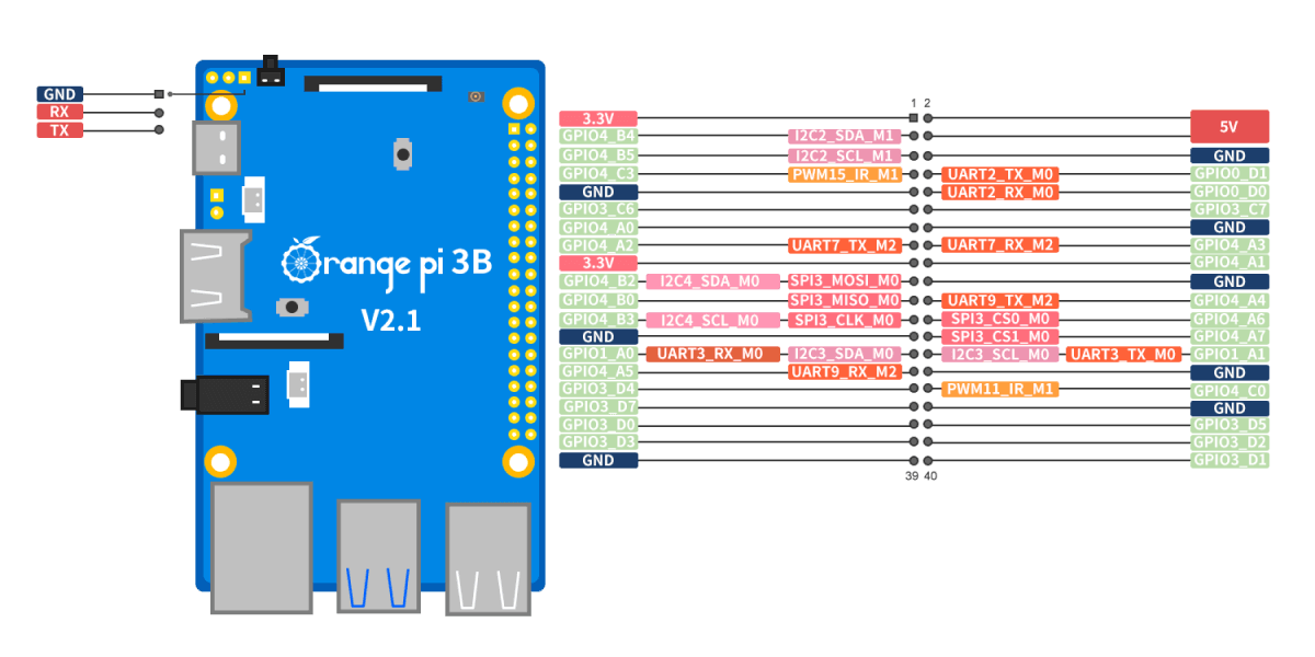
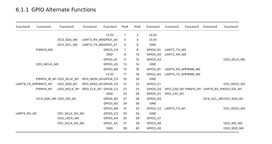
EDIT: Surprisingly different, especially the I2C2, exposed on pins 3/5 on the Orange Pi 3B, is not attached to the GPIO header at all on the Radxa Zero 3W, but instead to the CSI slot?

@MichaIng

I have to give up on the Radxa board for now; if unlocking it depends on that overlay I mentioned, I need a specific USB cable—one I have at home but didn’t bring along while visiting my parents :wink:

I studied the datasheets closely before buying the Zero 3W, and it seems feasible to attach a PCM5122 to it using the same pins (3, 5, 12, 35, and 40) on the 40-pin HAT connector. I’d just need to create a specific DTBO for the RK3566T—distinct from the standard RK3566—since those pins are actually connected to the I2S3 and I2C3 buses.
So, that’s a project for later.

For now, I’m going to test it on an Orange Pi Zero 2W I have here, which I can tinker with :wink:

For the my-soundcard perhaps it’s better to call this part just sound and delete the sound part at the end of this section because in the device tree this node is declared as sound in the initial dtb file when you read the dtsi

In case of the Radxa ZERO 3W, pin 3 and 5 are UART3, or GPIO1_A0 + GPIO1_A1 respectively. I2C2 is not available as function on any pin of the GPIO header. So you’d need to use a different I2C bus.

Not sure whether this is RK3566 vs RK3566T, or an per-SBC choice in this case. Looping through some other RK356x, the Radxa Zero 3 (W+E) seem to be quite a special/rare case, settings its GPIO line names explicitly: https://git.kernel.org/pub/scm/linux/kernel/git/stable/linux.git/tree/arch/arm64/boot/dts/rockchip/rk3566-radxa-zero-3.dtsi#n108
But not sure whether this means that most other RK356x SBCs follow a default to rely on, or whether the Radxa ZERO 3 is an exception in making GPIO => pins mapping visible, so that e.g. gpioinfo shows them properly.

Your’re right for the exeption of the radxa board

For my knowledge of the RK3566 , and for the orangepi board it’s the same pinout for the OPI 3b and the CM4 and his base board , this two board works with my PCM5102A’s script so this two board accept the PCM5122’s script :wink:

For the radxa a quick response here
Radxa zero 3w product brief
with this

Right, that moreless matches also the docs I linked: https://docs.radxa.com/en/zero/zero3/hardware-design/hardware-interface#gpio-interface

But an interesting difference, as pins 3 + 5 are of particular interest, is that the PDF shows I2C3 there as 3rd function, while I2C3 is not shown at all in the docs :thinking:.

Docs say:

compatible with most SBC accessories on the market.

PDF says:

compatible with many accessories on the market.

I’d probably says:

compatible with less accessories on the market, than you would expect, since a lot of GPIOs and buses are wired differently, than on most other RK356x boards.

At least any power out and ground pins are the same, so it shouldn’t be possible to cause permanent hardware damage. Either it works, or it doesn’t, after which one can disable the overlay again. Of course, when implementing it as sound card option in dietpi-config, we can hide it on Radxa ZERO 3, knowing about the incompatibility.

Hello @MichaIng
I test a rewrite of the pcm5122 dts part and the answer is
the name `my-soundcard` natively avoids any merge conflicts (the notorious parse errors) with DietPi’s default audio configurations. The Linux kernel then creates my sound card in parallel, in a completely stable manner. Therefore, you must retain the `my-soundcard` syntax and the `sound` sub-node.

so the last scrpt stay like that :wink: