Odroid C4 and hardkernel RTC PCF8563 or the need for synced time on read only system

Hi there,

I just trying to get to run hardkernel RTC module with odroid C4 and dietpi.

There are already some other threads here in forum which asks for support for other odroid versions without any solution.

Are there any news with working overlays to get this fxed?

My problem is not really the RTC module itself but the time which is missing sometimes when I boot on my read only system. Chromium boots to show home assistance panel which also shows google calendar and it is often the wrong date (date of storage freeze).

The work around I am aware of is to wait for NTP sync before starting chromium or even have a working hardware RTC module.

Any other thoughts?

BR, Sven

Answering my self with some progress:

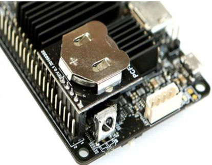
First of all I have tested rtc module with aardvark i2c usb adapter - it responds on address 0x51. So I assume, the module is working.
After I connected the module to odroid I just checked the supply voltage which shows 3.3V.

In dietpi I have done the following:

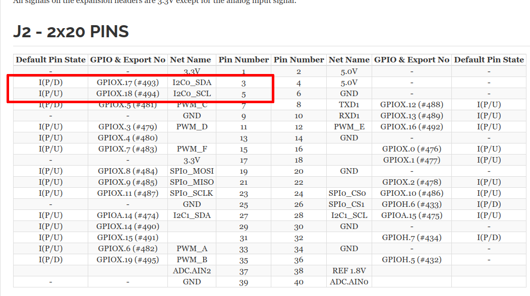
  1. Created a file with nano /boot/dtb/amlogic/overlay/meson-i2c0.dts Note: i2c2 is the one to use for odroid C4 on pins 17 and 18.
/plugin/;
/ {
        fragment@0 {
                target = <&i2c2>;

                __overlay__ {
                        status = "okay";
                        pinctrl-names = "default";
                        clock-frequency = <100000>;
                };
        };
};
  1. Compiled with dtc dtc -I dts -O dtb -o meson-i2c0.dtbo -@ meson-i2c0.dts
  2. Enabled overlay with nano /boot/dietpiEnv.txt and adding i2c0 to overlays
  3. reboot
  4. Check for second occuring i2c bus (other one is the hdmi bus):
ls -l /dev/i2c*
find /proc/device-tree/ -type d -name '*i2c*' -exec ls -l {}/status \; -exec cat {}/status \; -exec echo \; 2> /dev/null
crw-rw---- 1 root i2c 89, 0 21. Feb 17:02 /dev/i2c-0
crw-rw---- 1 root i2c 89, 1 21. Feb 17:02 /dev/i2c-1
-r--r--r-- 1 root root 9 21. Feb 17:09 /proc/device-tree/soc/bus@ff800000/i2c@5000/status
disabled
-r--r--r-- 1 root root 5 21. Feb 17:09 /proc/device-tree/soc/bus@ffd00000/i2c@1d000/status
okay
-r--r--r-- 1 root root 9 21. Feb 17:09 /proc/device-tree/soc/bus@ffd00000/i2c@1f000/status
disabled
-r--r--r-- 1 root root 9 21. Feb 17:09 /proc/device-tree/soc/bus@ffd00000/i2c@1c000/status
disabled
-r--r--r-- 1 root root 9 21. Feb 17:09 /proc/device-tree/soc/bus@ffd00000/i2c@1e000/status
disabled
  1. scanning with i2cdetect shows up no device: i2cdetect -y 0:
     0  1  2  3  4  5  6  7  8  9  a  b  c  d  e  f
00:                         -- -- -- -- -- -- -- -- 
10: -- -- -- -- -- -- -- -- -- -- -- -- -- -- -- -- 
20: -- -- -- -- -- -- -- -- -- -- -- -- -- -- -- -- 
30: -- -- -- -- -- -- -- -- -- -- -- -- -- -- -- -- 
40: -- -- -- -- -- -- -- -- -- -- -- -- -- -- -- -- 
50: -- -- -- -- -- -- -- -- -- -- -- -- -- -- -- -- 
60: -- -- -- -- -- -- -- -- -- -- -- -- -- -- -- -- 
70: -- -- -- -- -- -- -- -- 

My guess is that something is still missing in the overlay (configure IOs).

Here some links I have followed so far:

Are you sure about your wiring?

As I use the original hardkernel shield and also checked the right position I would say yes:
https://wiki.odroid.com/accessory/add-on_boards/rtc_shield

Possibly I could check with oscilloscope if there is something happening on the pins.

I have also tested the other 4 i2c channel with RTC module on i2c2 position but without any luck.

I just added the following code snippet to chromium-autostart.sh to get the timing issue solved:

# Just wait for synchronized NTP time
while ! timedatectl show -p NTPSynchronized | grep -q yes; do
  sleep 1
done


Judging by the picture, this one uses the i2c bus wired to pin 3 and 5, not the ones you noted.
Does the RTC show up when you run meson-sm1-odroid-c4.dtb.txt (49.8 KB)
Remove the .txt extension as it needs to be attached in order to post it on this forum.
Swap it out for your existing one and disable any overlay additions you currently have applied.
It has anything necessary aplied staticly and is wired to control the i2c2 IP at pins 3 and 5 to drive a pcf8563.
The kernel has to have the pcf8563 driver build (CONFIG_RTC_DRV_PCF8563).

I think we speak about the same pins.

I have replaced the file /boot/dtb/amlogic/meson-sm1-odroid-c4.dtb with yours and now it looks better.

ls /dev/i2c*
/dev/i2c-0  /dev/i2c-1
i2cdetect -l
i2c-0	i2c       	Meson I2C adapter               	I2C adapter
i2c-1	i2c       	DesignWare HDMI                 	I2C adapter
i2cdetect -y 0
     0  1  2  3  4  5  6  7  8  9  a  b  c  d  e  f
00:                         -- -- -- -- -- -- -- -- 
10: -- -- -- -- -- -- -- -- -- -- -- -- -- -- -- -- 
20: -- -- -- -- -- -- -- -- -- -- -- -- -- -- -- -- 
30: -- -- -- -- -- -- -- -- -- -- -- -- -- -- -- -- 
40: -- -- -- -- -- -- -- -- -- -- -- -- -- -- -- -- 
50: -- UU -- -- -- -- -- -- -- -- -- -- -- -- -- -- 
60: -- -- -- -- -- -- -- -- -- -- -- -- -- -- -- -- 
70: -- -- -- -- -- -- -- --
dmesg | grep i2c
[    0.788458] i2c_dev: i2c /dev entries driver
dmesg | grep rtc
[    2.016454] meson-vrtc ff8000a8.rtc: registered as rtc0
[    2.016489] meson-vrtc ff8000a8.rtc: setting system clock to 1970-01-01T00:00:02 UTC (2)
[    2.016848] rtc-pcf8563 0-0051: /aliases ID 0 not available
[    2.018160] rtc-pcf8563 0-0051: low voltage detected, date/time is not reliable.
[    2.037577] rtc-pcf8563 0-0051: registered as rtc1

Many thanks for your help!

What is the source code of the dtb and how did you create it?

Wrote an overlay from scratch and applied it staticly to a current base DTB.

// SPDX-License-Identifier: (GPL-2.0+ OR MIT)
/dts-v1/;
/plugin/;

/ {
<------>compatible = "hardkernel,odroid-c4";
};

&{/aliases} { // &aliases
<------>rtc0 = "/soc/bus@ffd00000/i2c@1d000/rtc@51";
<------>rtc1 = "/soc/bus@ff800000/rtc@a8";
};

&{/soc/bus@ffd00000/i2c@1d000} {  // &i2c2
<------>pinctrl-0 = <&i2c2_sda_x_pins>, <&i2c2_sck_x_pins>;
<------>pinctrl-names = "default";
<------>status = "okay";

<------>rtc: rtc@51 {
<------><------>compatible = "nxp,pcf8563";
<------><------>reg = <0x51>;
<------>};
};

&{/soc/bus@ff600000/bus@34400/pinctrl@40} { // &periphs_pinctrl
<------>i2c2_sda_x_pins: i2c2-sda-x { };
<------>i2c2_sck_x_pins: i2c2-sck-x { };
};

I see the integrated RTC pushing itself forward as rtc0, so I have extended the overlay with an rtc1 alias, so that the battery-powered RTC is registered as rtc0 and the OS acquires a real time. See meson-sm1-odroid-c4.dtb.txt (49.9 KB) for reference.

Maybe its better to have actually an overlay for this and create a PR for integrating it in dietpi?

As you have now all ingredients at hand, it’s up to you to make this happen.
I don’t own the device nor do I use DietPi, so I’m not interested in it.

The alias works well to have the rtc as default module!

I have created an overlay (meson-odroid-c4-rtc.dts):

/dts-v1/;
/plugin/;

/ {
    compatible = "hardkernel,odroid-c4";

    fragment@0 {
	target-path = "/aliases";
	__overlay__ {
            rtc0 = "/soc/bus@ffd00000/i2c@1d000/rtc@51";
            rtc1 = "/soc/bus@ff800000/rtc@a8";
        };
    };

    fragment@1 {
        target = <&i2c2>;
        __overlay__ {
            status = "okay";
            pinctrl-names = "default";
            pinctrl-0 = <&i2c2_sda_x_pins>, <&i2c2_sck_x_pins>;
            clock-frequency = <400000>; // Optional: Set the I2C bus speed
            #address-cells = <1>;
            #size-cells = <0>;
            rtc: rtc@51 {
                compatible = "nxp,pcf8563";
                reg = <0x51>;
            };
        };
    };

    fragment@2 {
        target-path = "/soc/bus@ff600000/bus@34400/pinctrl@40";
        __overlay__ {
            i2c2_sda_x_pins: i2c2-sda-x { };
            i2c2_sck_x_pins: i2c2-sck-x { };
        };
    };
};

dtbo file can be simply created from dts via dtc or I could commit directly.

Maybe a dietpi maintainer jumps in to give a hint where to PR dts and dtbo.

Something @MichaIng can decide on

This is not a real overlay source, but only the disassembly of the overlay, the correct source of which I already gave in my penultimate post.
And since my source code is written in absolute path notation, it can even be applied to a base DTB compiled without symbol bloat (-@).
I have added the source again as an attachment to this post, because the forum software has garbled the tabs in it in the display.
meson-sm1-odroid-c4-rtc.dtso.txt (572 Bytes)