I’ve done a lot of searching but haven’t found any tutorial about how to create a simple alarm digital clock with MAX7219 Matrix Led 4x8x8 (nice piece of hardware), all the tutorials I found are just for Arduino ![]()
So I decided to create my own one ![]() .
.
This is the complete and simple tutorial.
Total cost: about 60 Euro
Difficulty = easy
Time = 1 hour
Skills required = dummy >>
Hardware requisites:
- one 5V 3A power supply, or better two: one 5V 2A for “Raspberry + amplifier” and one 5V 1A for “Led matrix”.
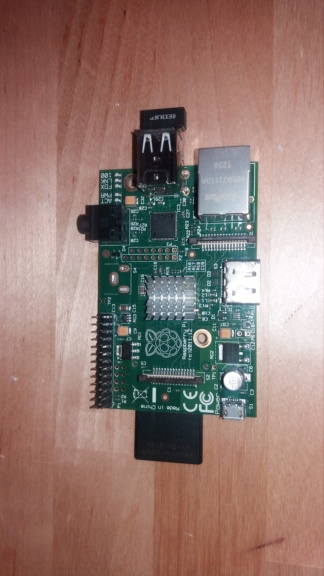
- Raspberry Pi1 512 or above
- Raspbian Stretch Lite on 4 GB sd card (or bigger)
- USB Wifi dongle - optional (for Pi1 and Pi2, not needed for Pi3)
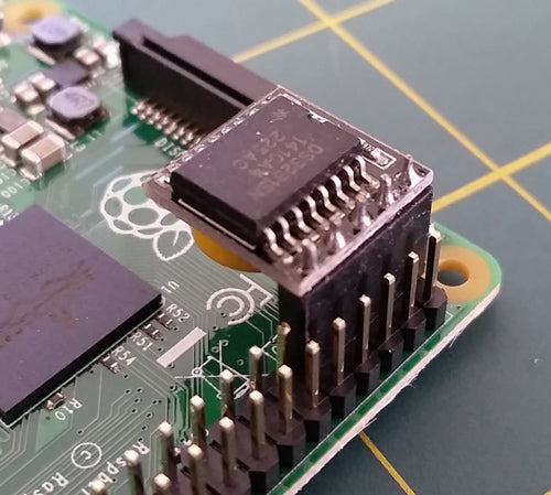
- RTC Module (DS3231 suggested)
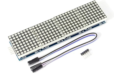
- MAX7219-LED-4x8x8-Matrix
- 5V 2W mini audio amplifier (mono is OK)
- 2W Mini speaker(s)
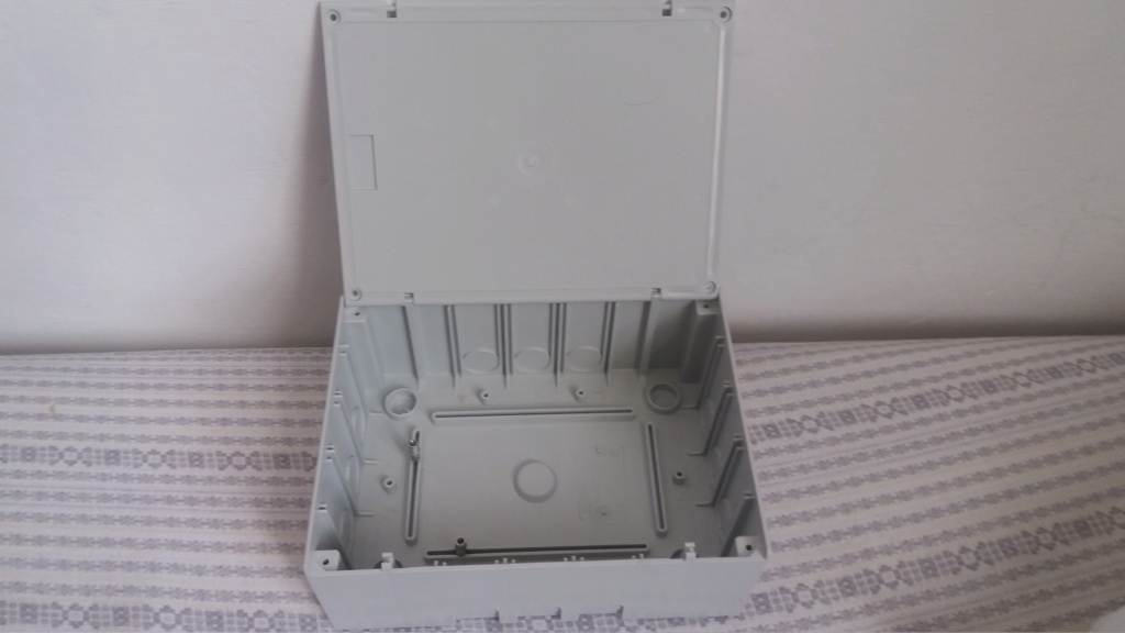
- a plastic box
- some wires (arduino jumper wires)
Max Mem usage: less than 100 Mbytes
Max CPU usage: less than 30% @ RP1 no overclock
Important Notes:
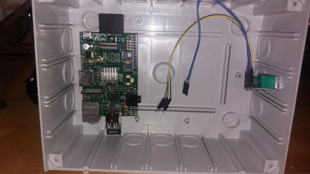
connect the Vcc pin of the Led Matrix directly to the 5V of the power supply, do not connect it to the Raspberry +5V pins.
All GND pins (‘ground’ or ‘-’) of Raspberry, Amplifier and MAX7219 Led matrix, need to be connected together (just one pin per board)
The audio amplifier gets +5V directly to the +5V (pin 2 or 4) of the raspberry
Raspberry
RTC
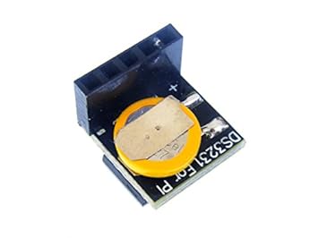
RTC installation
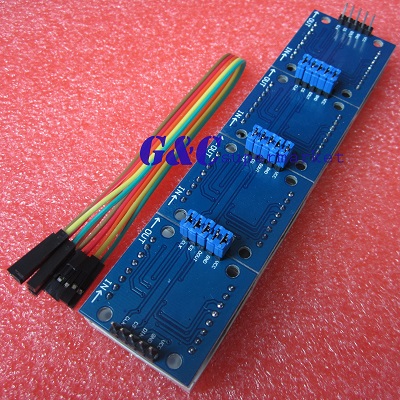
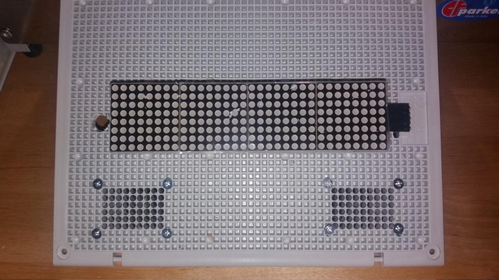
MAX7219 Led Matrix module
Pin-out description on the bottom side
BOX

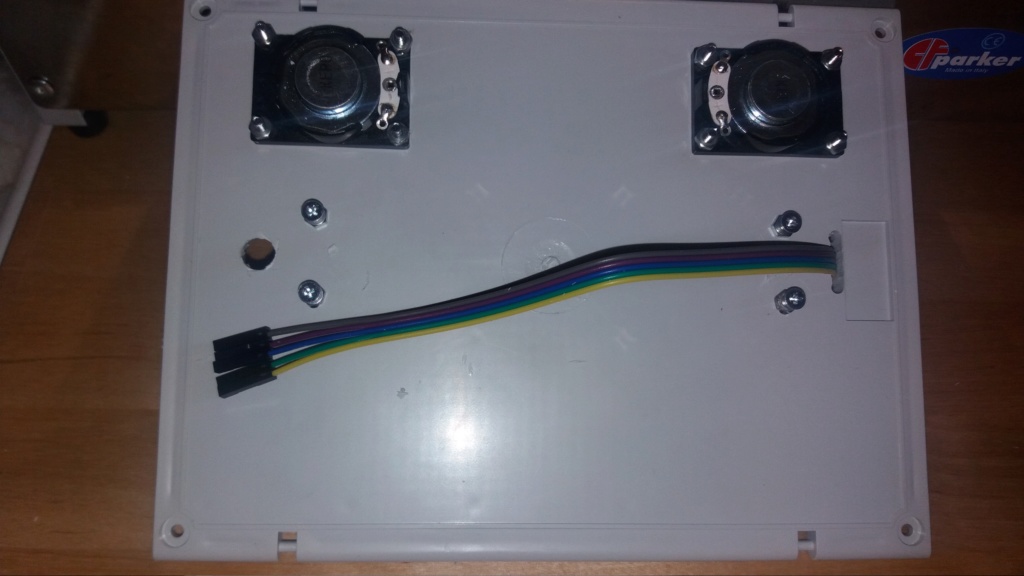
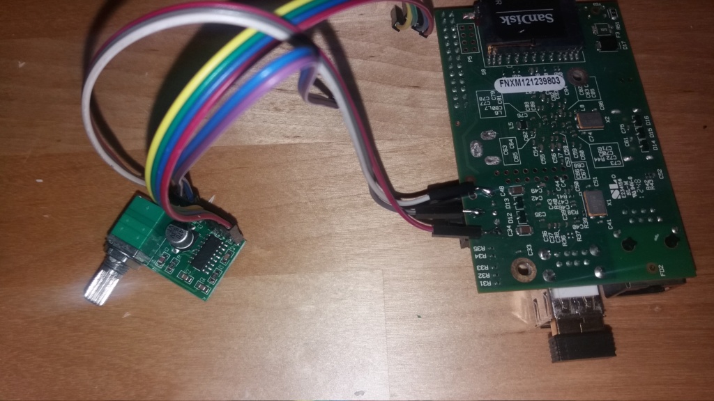
Stereo mini audio amplifier
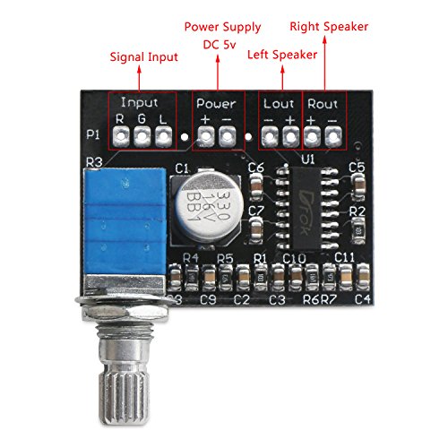
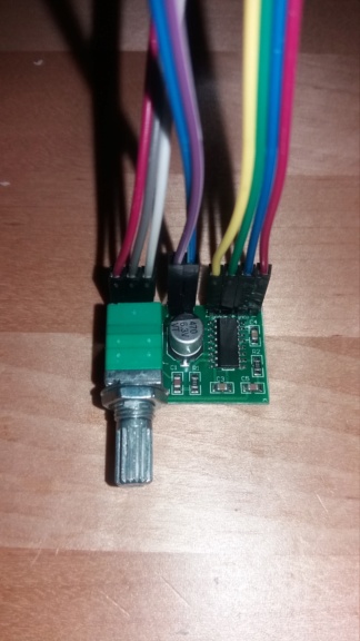
I decided to solder the audio wires from raspberry to the amp, but you can use the 3.5 audio connector as well.
Finished project ![]()
note: in this picture the TIME is shifted to the right, I modified the code to better center it, also the leds bright is settable (see code comments)
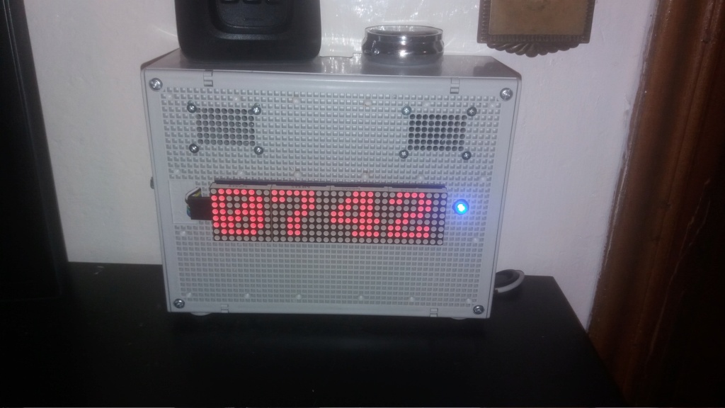
You can also add scrolling text to the clock (there is a little startup demo in my code):
You might use Raspberry Zero, but you need a mini adapter like this, to have an audio connection output (HDMI to VGA/Audio):
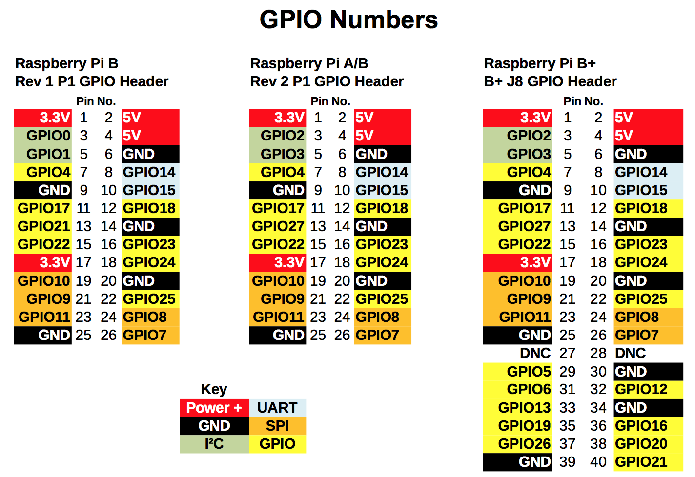
Raspberry GPIO pin-outs (needed for connecting MAX7219-LED matrix)