Hey @Totof , I appreciate the suggestions!
Unfortunately, I still only hear the same first “pop” sound then nothing.
Here are details of what I tried:
I’ve updated /etc/asound.conf to the following as you advised then rebooted.
cat /etc/asound.conf
pcm.device {
        format S16_LE
        rate 44100
        type hw
        card 0
        device 0
}

pcm.!default {
        type plug
        slave.pcm "device"
}

ctl.!default {
        type hw
        card 0
}
After reboot, tried aplay:
aplay -D hw:0,0 /usr/share/sounds/alsa/Front_Left.wav
Playing WAVE '/usr/share/sounds/alsa/Front_Left.wav' : Signed 16 bit Little Endian, Rate 48000 Hz, Mono
Only hear the same “pop” sound at the very beginning then no sound.
Same result with the Front_Right.wav.
I’ve also tried with these amixer settings, but same result.
amixer -D hw:0 -c 0 set 'Left Output Mixer DACL' 100% unmute
Simple mixer control ‘Left Output Mixer DACL’,0
Capabilities: pswitch pswitch-joined
Playback channels: Mono
Mono: Playback [on]
amixer -D hw:0 -c 0 set 'Left Output Mixer DACR' 100% unmute
Simple mixer control ‘Left Output Mixer DACR’,0
Capabilities: pswitch pswitch-joined
Playback channels: Mono
Mono: Playback [on]
amixer -D hw:0 -c 0 set 'Right Output Mixer DACL' 100% unmute
Simple mixer control ‘Right Output Mixer DACL’,0
Capabilities: pswitch pswitch-joined
Playback channels: Mono
Mono: Playback [on]
amixer -D hw:0 -c 0 set 'Right Output Mixer DACR' 100% unmute
Simple mixer control ‘Right Output Mixer DACR’,0
Capabilities: pswitch pswitch-joined
Playback channels: Mono
Mono: Playback [on]
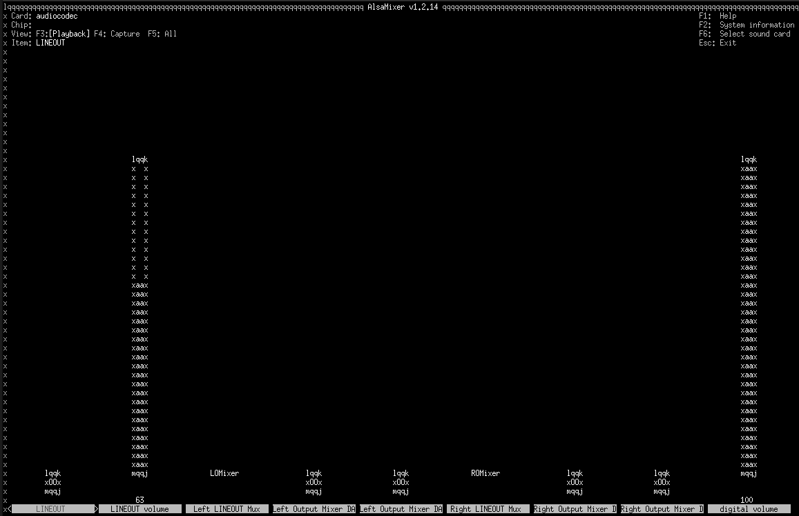
amixer -D hw:0 -c 0 set 'LINEOUT volume' 100% unmute
Simple mixer control ‘LINEOUT volume’,0
Capabilities: volume volume-joined
Playback channels: Mono
Capture channels: Mono
Limits: 0 - 31
Mono: 31 [100%] [1.50dB]
amixer -D hw:0 -c 0 set 'digital volume' 100% unmute
Simple mixer control ‘digital volume’,0
Capabilities: volume volume-joined
Playback channels: Mono
Capture channels: Mono
Limits: 0 - 63
Mono: 63 [100%] [41214.60dB]