Hello everyone
I tested the jack connector and the HDMI for the sound, it’s okay with the script
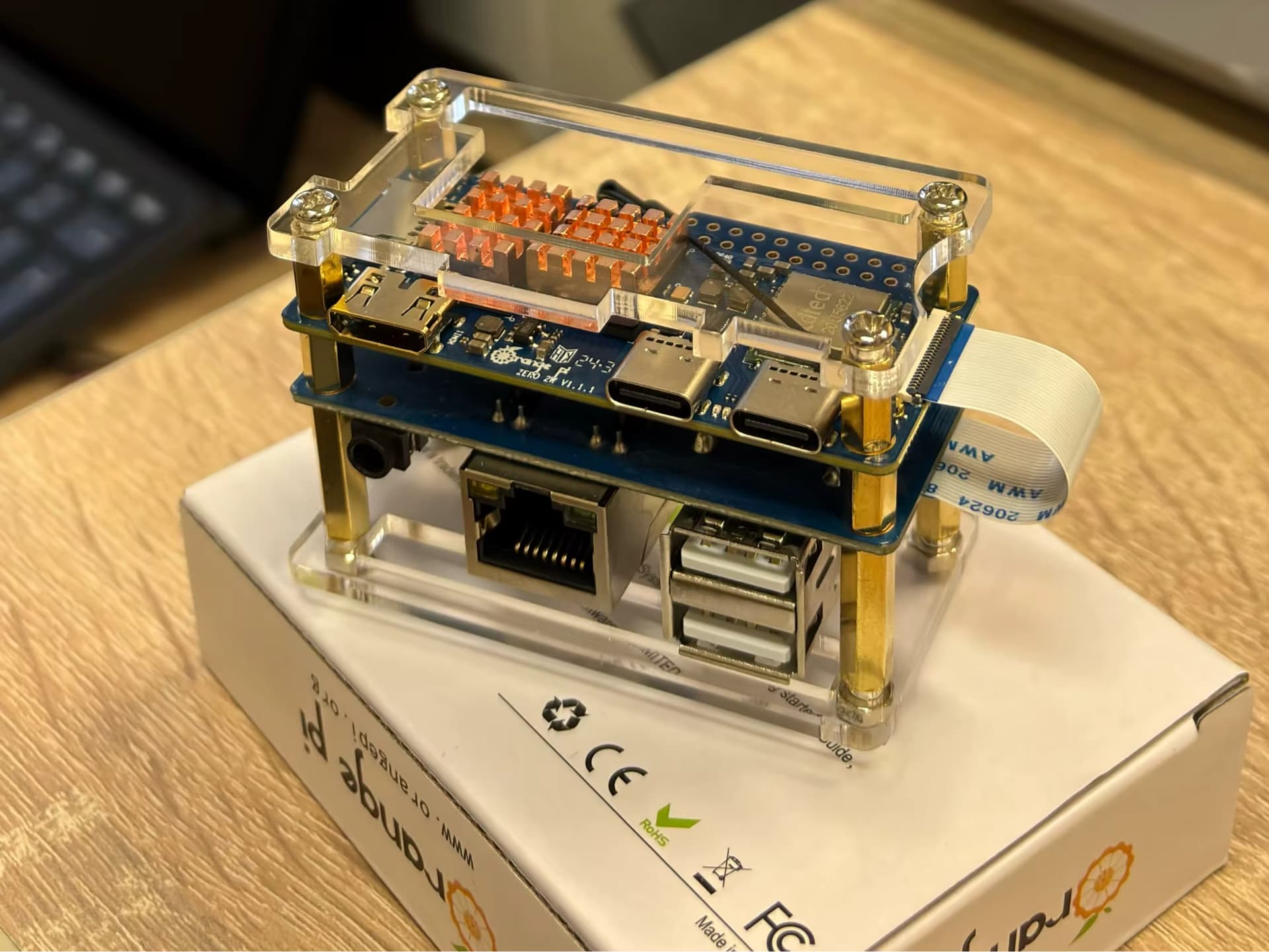
I receive my PCM5102 so i tested and i need to make some change in the script
i need to implement clock and some parts to have sound with the PCM5102
Now it’s done and work very well
@MichaIng just one item doesn’t work in the script , the command line “G_CONFIG_INJECT”
Perhaps you can help me to implement it
This line found in the forum can do the job ?
# DietPi-Globals: dietpi-* aliases, G_* functions and variables
. /boot/dietpi/func/dietpi-globals || { echo -e '[\e[31mFAILED\e[0m] DietPi-Login | Failed to load DietPi-Globals. Skipping DietPi login scripts...'; return 1; }
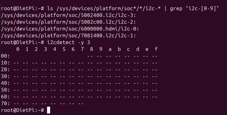
So the new script to obtain sound with the PCM5102 on the 40pin hat
# Create the directory for user overlays
mkdir -p /boot/overlay-user
cd /boot/overlay-user
# Create the overlay source file
cat << '_EOF_' > sound-hdmi-jack-i2s0-hat.dts
/dts-v1/;
/plugin/;
/ {
compatible = "allwinner,sun50i-h618";
fragment@0 {
target = <&pio>;
__overlay__ {
ahub_daudio0_pins_d: ahub_daudio0_sleep {
pins = "PI0", "PI1", "PI2", "PI3", "PI4";
function = "gpio_in";
drive-strength = <0x14>;
bias-disable;
};
ahub_daudio0_pins_a: ahub_daudio0@0 {
pins = "PI0", "PI1", "PI2";
function = "i2s0";
drive-strength = <0x14>;
bias-disable;
};
ahub_daudio0_pins_b: ahub_daudio0@1 {
pins = "PI3";
function = "i2s0_dout0";
drive-strength = <0x14>;
bias-disable;
};
ahub_daudio0_pins_c: ahub_daudio0@2 {
pins = "PI4";
function = "i2s0_din0";
drive-strength = <0x14>;
bias-disable;
};
};
};
fragment@1 {
target-path = "/soc";
__overlay__ {
ahub0_plat: ahub0_plat {
#sound-dai-cells = <0>;
compatible = "allwinner,sunxi-snd-plat-ahub";
apb_num = <0>; /* for dma port 3 */
dmas = <&dma 3>, <&dma 3>;
dma-names = "tx", "rx";
playback_cma = <128>;
capture_cma = <128>;
tx_fifo_size = <128>;
rx_fifo_size = <128>;
pinctrl-names = "default", "sleep";
pinctrl_used;
pinctrl-0 = <&ahub_daudio0_pins_a>, <&ahub_daudio0_pins_b>, <&ahub_daudio0_pins_c>;
pinctrl-1 = <&ahub_daudio0_pins_d>;
status = "okay";
};
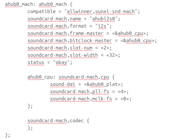
ahub0_mach: ahub0_mach {
compatible = "allwinner,sunxi-snd-mach";
soundcard-mach,name = "ahubi2s0";
soundcard-mach,format = "i2s";
soundcard-mach,frame-master = <&ahub0_cpu>;
soundcard-mach,bitclock-master = <&ahub0_cpu>;
soundcard-mach,slot-num = <2>;
soundcard-mach,slot-width = <32>;
status = "okay";
ahub0_cpu: soundcard-mach,cpu {
sound-dai = <&ahub0_plat>;
soundcard-mach,pll-fs = <4>;
soundcard-mach,mclk-fs = <0>;
};
soundcard-mach,codec {
};
};
};
};
fragment@2 {
target-path = "/soc";
__overlay__ {
codec: codec {
compatible = "allwinner,sun50i-h616-codec";
status = "okay";
allwinner,audio-routing = "Line Out", "LINEOUT";
};
};
};
fragment@3 {
target-path = "/soc";
__overlay__ {
ahub_dam_plat: ahub_dam_plat {
compatible = "allwinner,sunxi-snd-plat-ahub_dam";
status = "okay";
};
};
};
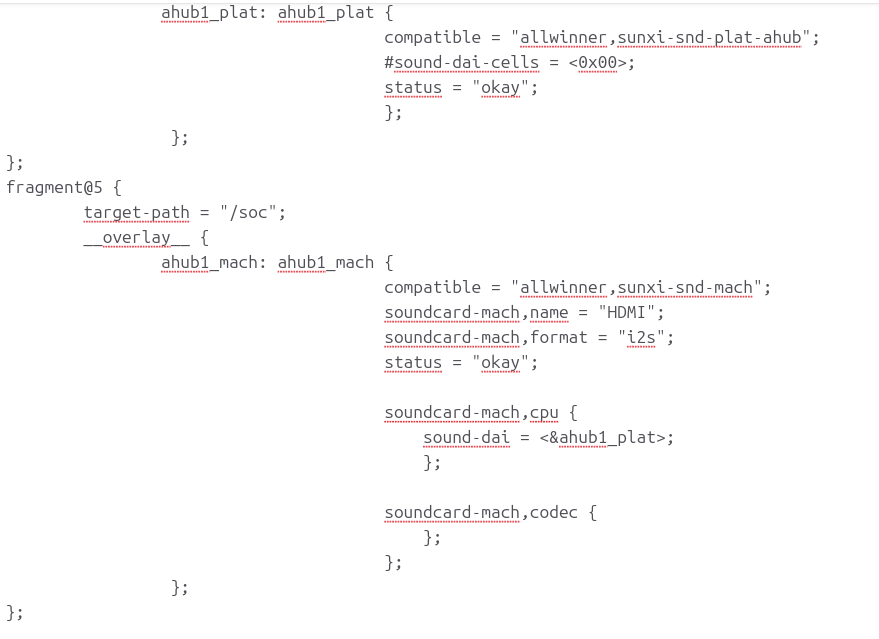
fragment@4 {
target-path = "/soc";
__overlay__ {
ahub1_plat: ahub1_plat {
compatible = "allwinner,sunxi-snd-plat-ahub";
#sound-dai-cells = <0x00>;
status = "okay";
};
};
};
fragment@5 {
target-path = "/soc";
__overlay__ {
ahub1_mach: ahub1_mach {
compatible = "allwinner,sunxi-snd-mach";
soundcard-mach,name = "HDMI";
soundcard-mach,format = "i2s";
status = "okay";
soundcard-mach,cpu {
sound-dai = <&ahub1_plat>;
};
soundcard-mach,codec {
};
};
};
};
};
_EOF_
# Install the device tree compiler
apt install device-tree-compiler
# Compile the overlay binary file
dtc -I dts -O dtb -o sound-hdmi-jack-i2s0-hat.dtbo -@ sound-hdmi-jack-i2s0-hat.dts
# To see the result of the compiler uncommit next line
#fdtdump sound-hdmi-jack-i2s0-hat.dtbo
# Enable the user overlay via U-Boot environment file
G_CONFIG_INJECT 'user_overlays=' 'user_overlays=sound-hdmi-jack-i2s0-hat' /boot/dietpiEnv.txt
A little bit busy in this moment withwork and sport but next week on holiday
so i try to implement with an user overlay a cheap PCM5122 dac board